 English
 Español
1. Power light is off
electricity failure
12 to 48 cores doom Mechanical seal fiber optic splitter closure 2 inlet 2 outlet
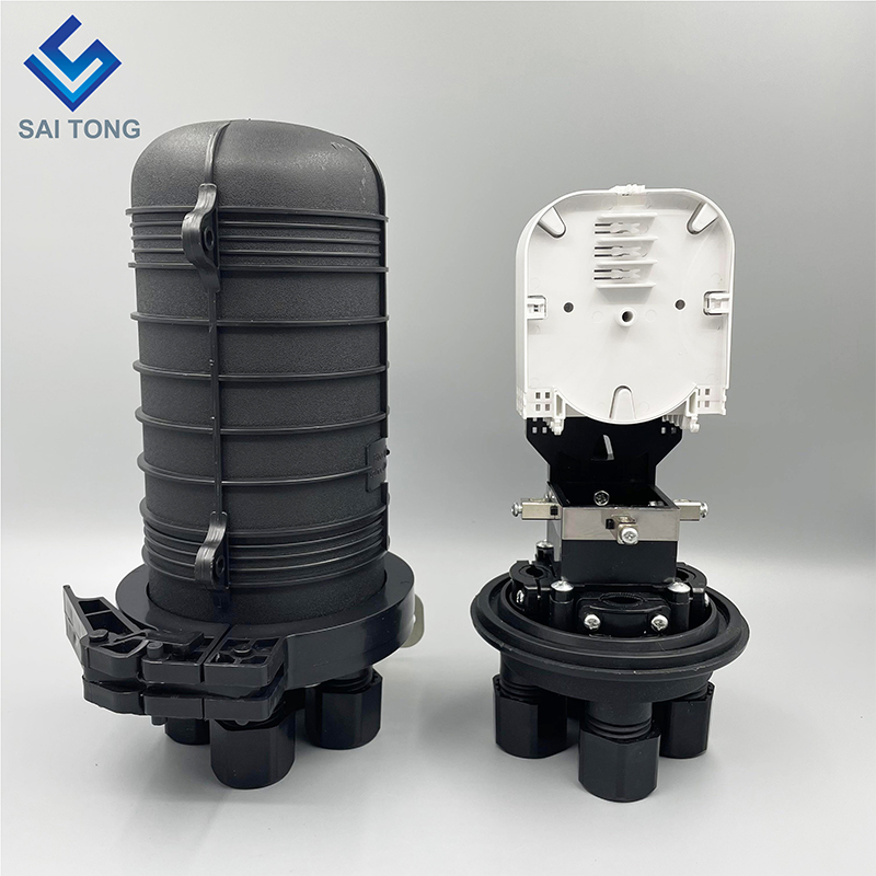
12 to 48 cores doom Mechanical seal fiber optic splitter closure 2 inlet 2 outlet
Description:
Optical Splice Closures Are Used To Distribute, Splice, And Store The Outdoor Optical Cables Which Enter And Exit From The Ends Of The Closure. There Are Two Connection Ways: Direct Connection And Splitting Connection. They Are Applicable To Situations Such As Overhead, Man-Well Of Pipeline, Embedded Situation Etc. Comparing With Terminal Box,The Closure Requires Much Stricter Requirement Of Seal. Sealing Ring And Air Valve Are Required For Closure, But That Are Not Necessary For Terminal Box.
Features:
1). High Quality PPR Material Optional, Can Ensure Harsh Conditions Such As Vibration, Impact, Tensile Cable Distortion And Strong Temperature Changes.
2). Solid Structure, Perfect Outline, Thunder, Erosion And Adding Resistance.
3). Strong And Reasonable Structure With Mechanical Sealing Structure, Can Be Opened After Sealing And Cab Be Reused.
4). Well Water And Dust Proof, Unique Grounding Device To Ensure The Sealing Performance, Convenient For Installation.
5). The Splice Closure Has A Wide Application Range, With Good Sealing Performance, Easy Installation, Produced With High Strength Engineering Plastic Housing, With Anti-Aging, Corrosion Resistance, High Temperature And High Mechanical Strength And So On.
2. If the Link light is off, the fault may be as follows:
(a) Check whether the optical fiber line is disconnected
(b) Check whether the loss of the fiber optic splice closure line is too large, beyond the receiving range of the equipment
(c) Check whether the optical fiber interface is connected correctly, the local TX is connected to the remote RX, and the remote TX is connected to the local RX.
(d) Check whether the fiber optic connector is inserted into the device interface in good condition, whether the jumper type matches the device interface, whether the device type matches the optical fiber, and whether the transmission length of the device matches the distance.
3. The link light of the circuit is not on. The fault may be as follows:
(a) Check whether the network cable is broken
(b) Check whether the connection types match: use crossover cables for network cards and routers, and use straight-through cables for switches, hubs and other devices.
(c) Check whether the transmission rate of the device matches
4. Severe network packet loss, the possible faults are as follows:
(1) The electrical port of the transceiver does not match the duplex mode of the network device interface, or the device interfaces at both ends.
(2) There is a problem with the twisted pair and the RJ-45 head, check it
(3) Fiber connection problems, whether the jumper is aligned with the device interface, whether the pigtail matches the jumper and coupler type, etc.
5. After the fiber optic transceiver is connected, the two ends cannot communicate
(1) The optical fiber is reversed, and the optical fiber connected to TX and RX is reversed
(2) The connection between the RJ45 interface and the external equipment is not correct (pay attention to straight-through and splicing). The optical fiber interface (ceramic ferrule) does not match. This fault is mainly reflected in the 100M transceiver with photoelectric mutual control function, such as the end of the APC ferrule. If the fiber is connected to the transceiver of the PC ferrule, it will not be able to communicate normally, but it will not be affected if it is connected to a non-optical mutual control transceiver.
6. On and off phenomenon
(1) It may be that the optical path attenuation is too large. At this time, an optical power meter can be used to measure the optical power at the receiving end. If it is near the receiving sensitivity range, it can be basically judged as an optical path failure within the range of 1-2dB.
(2) It may be that the switch connected to the transceiver is faulty. At this time, replace the switch with a PC, that is, the two transceivers are directly connected to the PC, and both ends are PING. If there is no intermittent connection, it can be basically judged as a switch failure.
(3) It may be a transceiver failure. At this time, connect both ends of the transceiver to the PC (not through a switch). After the two ends have no problem with PING, transfer a large file (100M) or more from one end to the other end, and observe it. If the speed is very slow (file transfer below 200M takes more than 15 minutes), it can be basically judged that the transceiver is faulty
7. After a period of communication, it crashes, that is, it cannot communicate, and it returns to normal after restarting
This phenomenon is generally caused by the switch. The switch will perform CRC error detection and length check on all received data, and discard the packets with errors, and forward the correct packets. The editor of Lanzhou Optical Fiber Recycling Co., Ltd. reminds everyone that some erroneous packets in this process cannot be detected in CRC error detection and length verification. Such packets will not be sent out during the forwarding process, nor will they be discarded. They will be accumulated in the dynamic buffer (buffer) and can never be sent out. When the buffer is full, it will cause the switch to crash. Because at this time, restarting the transceiver or restarting the switch can restore the communication to normal, so users usually think that it is a problem with the transceiver.


